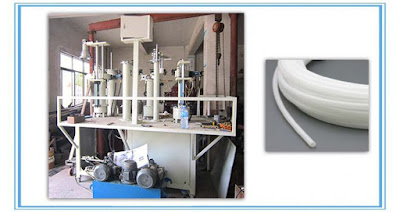
A vertical press machine for PTFE Tube

Vertical press machine for PTFE tube;Using for Pre-sintering PTFE material;Suit for new PTFE material or Recycle PTFE material;Rangeof diameter PTFE Extrusion 20-500 mm, Heating zones 5 zones; Automatic.
vertical press machine
Vertical press machiner is to extrude PTFE/UHMWPE Tubes. It is designed using latest technology, fully reliable and easy to operate for customers. Performance in terms of production and working hour capacity is competitive to other machines. Low  maintenance is required , giving  high production  in market.
1. Save time and money, good advantage price offer to customers.
2. Intelligent and easy-to-use operations.
3. Small workplace required due to its compact design and electricity saving machine.
4. Super quality output and the physical properties is adjustable.
5. Precise temperature control, reaches + -1 degree.
6. Long- life, with modern technology and optimized design.

Fluoric polymers (PTFE/PVDF)

Fluoropolymers have excellent, almost universal chemical resistance. They can be used both at high and very low temperatures (-260 to +260°C). They also possess outstanding resistance to weathering (UV-stability).
Due to the low coefficient of friction, they are often used as sliding materials or as corresponding additives in other high-performance plastics.

TECAFLON PVDF (PVDF)

Polyvinylidenefluoride (PVDF) – TECAFLON PVDF – is an opaque, semi-crystalline, thermoplastic fluoropolymer. PVDF is characterized by excellent chemical stability, without having the disadvantages of low-mechanical values and/or processing difficulties which can be experienced with other fluoroplastics.
  • low density compared to other fluoropolymers
    good mechanical strength compared to other fluoropolymers
    high permanent operating temperature (140°C)
    practically no moisture absorption
    good dimensional stability
    high chemical resistance
    good resistance to hydrolysis
    weather-proof
    radiation resistant
    good electrical insulator
    high abrasion resistance

TECAFLON PTFE natural (PTFE)

Polytetrafluoroethylene (PTFE) – TECAFLON PTFE natural – is a semi-crystalline fluoropolymer with an unusually high chemical and thermal resistance (-200 to +260°C, temporarily up to 300°C). In addition, this thermoplastic material has excellent sliding properties, a non-stick surface and the best insulating properties. This is in contrast, however, to low mechanical strength and a high specific gravity, compared to other plastics. In order to improve the mechanical properties, PTFE can be used as a compound reinforced with additives such as glass fibre, carbon or bronze. Due to its structure, this material is formed into semi-finished products using a compression processes and machined afterwards with cutting/machining tools.
  • extremely high chemical resistance
    very good temperature resistance (-200-+260°C, temporarily up to 300°C)
    very low coefficient of friction (static friction = sliding friction)
    extremely low surface tension (practically no materials stick to PTFE -> difficult to adhere to or weld)
    high coefficient of thermal expansion
    relatively low strength/rigidity
    low dielectric constant
    non-combustible

Single Screw Extruder

Single screw extrusion is one of the core operations in polymer processing and is also a key component in many other processing operations. The foremost goal of a single screw extrusion process is to build pressure in a polymer melt so that it can be extruded through a die or injected into a mold. Most machines are plasticating: they bring in solids in pellet or powder form and melt them as well as building pressure.
 
A single-screw extruder is a press which pushes material through its barrel under conditions of high pressure and temperature. It can produce objects of different length with a cross-section corresponding to the outlet opening.
Applications
The extrusion process melts the raw material and then hardens it once shaped. It can be applied to ceramics, rubber, thermoplastic polymers, pasta and other food products.
Technologies
These machines have a single screw turning within a cylinder, which is usually smooth. Raw material is fed into the barrel through a hopper and extruded into a die, which gives the material its final shape.
The barrel consists of three main zones: feed, compression and metering. The pressure increase within the extruder and movement of the material through the barrel are a function of screw geometry and the friction of the material against the screw and the barrel walls.

Multi-hole Ram Extrusion Process

Multi-hole ram extrusion is the process in which the raw material is pushed through a die having more than one hole. This process is highly productive for producing parts of smaller length and cross-section. For the given billet and final product size, the requirement of the ram force is lesser in the multi-hole extrusion than in the single-hole extrusion. The process has great importance for producing micron-size parts.
 
For the design of a multi-hole die extrusion machine, the modeling of the extrusion process is required. Although the finite element method can be effectively employed for this purpose, it requires a large amount of computational time besides the requirement of appropriate software to do the mesh generation and finite element processing. After the tentative or final specifications are decided, the design process usually consists of three stages: the conceptual design, the embodiment or preliminary design and the detailed design. At the conceptual design stage, the design concepts are generated. At the preliminary design stage, the chosen concept is given bodily form. Finally, at the detailed design stage, the detailed design calculations are carried out and the manufacturing drawings are generated. At the preliminary design stage, one needs computationally faster analysis for generating an optimum design. The generated design at this stage can be further fine tuned with rigorous finite element analysis of the process.
The estimation of the ram force is carried out using upper bound method by considering the process as a single-hole extrusion. This leads to an overestimation of the ram force, which results in a safer design of the die and ram. Die pressure distribution along the die face has been calculated using the slab method. A finite element analysis of the die has been carried out to estimate the distribution of the von-Mises stresses across the die volume. The experimental investigations have been carried out by extruding the billets made of lead through single-hole and multi-hole dies. The experimental results are compared with the analytical results. To carry out the analysis, the value of the friction factor is found experimentally. It is observed that the ram force calculated by the proposed methodology is about 25% greater than the experimental force for a single-hole extrusion. It is found experimentally that the material encounters more resistance to flow in the central hole than in the holes away from the center. This leads to differences in the lengths of the extruded wires, if the hole-sizes are same. In the case of the multihole extrusion, ram force is always lesser (about two-third) than in the case of the single-hole extrusion. Thus, the multi-hole extrusion process can become a productive process for the mass production of small sized components.

Fluoropolymers Properties

Fluoropolymers are produced from alkenes in which one or more hydrogen atoms have been replaced by fluorine. The most important members are polytetrafluoroethylene (PTFE), polychlorotrifluoroethylene (PCTFE), poly(vinyl fluoride) (PVF) and poly(vinylidene fluoride) (PVDF)
 
Due to the weak van der Waals forces, polyfluoroolefins have a very low coefficient of friction and very low surface tension and, due to the stability of the (multiple) carbon-fluorine bonds, excellent chemical resistance, which increases with the number of fluorine atoms in the repeat unit. They can be used both at high and very low temperatures and possess outstanding resistance to weathering (UV-resistance). Most fluoropolymers are also totally insoluble in most organic solvents and stable in concentrated acids and bases.
The largest-volume polyfluoroolefin is polytetrafluoroethylene (PTFE). This polymer has unique performance properties. It has outstanding thermal, electrical and chemical resistance and can be used both at very high (up to 530 K) and extremely low temperatures. Its coefficient of friction is among the lowest of all polymers (self-lubricating and non-stick). PTFE cannot be dissolved in any common solvent below its melting point. It is ideal for applications where broad chemical resistance, high durability, wide service temperature range, excellent dielectric properties, low friction, and non-stick are required. The properties of PTFE – high crystallinity, very high melting point (600 K), and very high melt viscosity – do not allow its processing by the usual process methods for plastics. Instead, similar to metal forming, the granular resins are processed by compression moulding at ambient temperature followed by sintering above the crystalline melting point.
Various copolymers of tetrafluoroethylene (PFA, FEP, ETFE) and other fluoropolymers with lower melting point and crystallinity were developed to overcome the lack of melt processability of PTFE. Among these, poly(vinylidene fluoride) (PVDF) is noteworthy. These resins are some of the easiest to process fluoropolymers. PVDF has high tensile and impact strength, and excellent resistance to tensile creep and fatigue. Like PTFE, it exhibits high thermal stability.
Another important, highly crystalline fluoropolymer is poly(vinylfluoride) (PVF). PVF films are strong, flexible and have good fatigue-resistance and can be used for applications in the temperature range from approximately 200 K to 380 K.

Applications

Fluoropolymer applications include electrical (coaxial cables for radio frequency, tapes, seat heating, appliance and aircraft wiring), chemical (lined pipe and fittings, gaskets, thread sealant tapes), mechanical (bearings, seals, piston rings, anti-stick coatings, self-lubricating parts) and filters and membranes.

Injection Moulding Process

Injection moulding is a two step cyclical process: (a) melt generation by a rotating screw, and (b) filling of the mouldwith molten polymer by the forward ramming of the screw (called a reciprocating screw), followed by a very short packing stage necessary to pack more polymer in the mould to offset the shrinkage after cooling and solidi cation. The material is held in the mould under high pressure until it has solidified suf ciently to allow ejection.
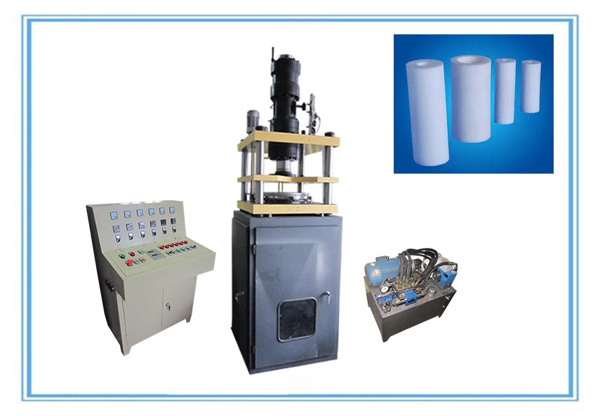
Tube ExtrusionPolymer injection molding has certain similarities to the die casting process of metals, in which molten metal is forced under high pressure into a steel mould or die. The metal, as the polymer, is pressed into all the crevices of the mould and the pressure is held while the metal freezes.
In polymer injection moulding, the melt path into the mould starts with a sprue, and splits off into individual runners each feeding one of the multiplicity of mould cavities through a gate. Moulds can contain over 100 cavities, each producing a part per injection cycle. Cycle times range from a few secondsto over a minute. Numerous productsranging from boat hulls, lawn chairs and appliance housings to radio knobs and bottle caps are injection moulded. Very high shear rates arise in injection moulding operations (usually up to 104 s21 ) and, to limit temperature increases from viscous heating and also to facilitate easy filling, low viscosity thermoplastic polymer grades are used.
Injection moulding machines are rated by the size of their clamping systems, which are hydraulic, electrical or mechanical toggle systems used to hold the mould closed with sufficient force to resist the injection pressure. Machines available usually range from 5 tons for a shot of ~10 g to 5000 tons for shots of more than 50 kg (shot is the total amount of material pumped into the mould in a cycle, including that in the sprue, runners and cavities). Some bigger machines have also been built for the production of very large moulded products. Micromoulding, in which the shot size is below 1 g, is recently finding increased use in biomedical and nanotechnological applications.
Simulation software is used extensively in the design of injection moulds, because of the ability of the Hele – Shaw flow approximation to describe reasonably well the mould filling process. More recently, however, three-dimensional models of flow simulation have come into use. Economics also provide an incentive for the use of software, as moulds can be extremely expensive to make, so minimising trial and error procedures on the factory oor is desirable. The software is used to design the part cavities, to balance runners, to visualise the filling process, and to predict orientation, shrinkage, warpage and weld lines in the product.
Among the challenging problems faced in computer simulation is the prediction of shrinkage and warpage. Shrinkage is the difference in dimensions between the mould and the cooled moulded part. The main cause is the density increase which occurs as the melt freezes. Crystalline poly- mers such as polyamide (PA, nylon), high density PE, PET and PP give the worst problems, with shrinkages of 1 – 4%. Amorphous polymers such as PS, PMMA and PC have fewer problems, shrinking only 0.3 – 0.7%. Warpage is caused by the density changes mentioned above, and orientation imparted to the part during cavity filling and packing, decidedly in a non-uniform manner.
Gas assist injection moulding involves the injection of nitrogen with the plastic, which creates a hollow void in the moulded part.This allows large parts to be moulded with lower clamp tonnage and signi cant material savings. This innovative process started in the 1980s and its use is rapidly growing.
The process of reaction injection moulding (RIM) involves the injection of low viscosity liquids, which become reactive when mixed and polymerise within the mould.The advantage of this processis that the pressures are low owing to the low viscosities. A disadvantage is the requirement to handle highly toxic substances. Although initial projections called for significant growth in RIM, this did not materialise. In fact, some manufacturers of automotive parts by RIM have switched to conventional injection moulding.

Source:http://ptfe-machinery.com/injection-moulding-process-injection-moulding-machines/

Extrusion machines for PTFE Medical tubing

Sunkoo PFG150 Single Screw Extruder Features:Vertical Ram Extruder for PTFE tube;Ram extruding machine for PTFE tube;Using for Pre-sintering PTFE material;Suit for new PTFE material or Recycle PTFE material;Rangeof diameter PTFE Extrusion 20-150 mm, Heating zones 5 zones; Automatic.
 
Sunkoo PFG150 Tube Extruder is to extrude PTFE/UHMWPE Tubes. It is designed using latest technology, fully reliable and easy to operate for customers. Performance in terms of production and working hour capacity is competitive to other machines. Low maintenance is required , giving high production in market.
Features:
  • Save time and money.
  • PLC design and easy to operate.
  • Long time span. No heating effect during operation.
  • With latest technology and optimized design.
  • Min – Max Dia:20-150mm.
  • Production Per Hour: 10+ kg/h.
  • Unlimited Length
  • Automatic operation.
  • 5 Heating Zones