Injection Molding Machines

Injection molding machines differ in both injection unit and clamping unit. The name of the injection molding machine is generally based on the type of injection unit used.
Injection Units. Two types of injection units are widely used today. The reciprocating-screw machine is the most common. This design uses the same barrel for melting and injection of plastic. The alternative unit involves the use of separate barrels for plasticizing and injecting the polymer. This type is called a screw-preplasticizer machine or two-stage machine. Plastic pellets are fed from a hopper into the first stage, which uses a screw to drive the polymer forward and melt it. This barrel feeds a second barrel, which uses a plunger to inject the melt into the mold. Older machines used one plunger-driven barrel to melt and inject the plastic. These machines are referred to as plunger-type injection molding machines.
injectionMolded7
Two alternative injection systems to the reciprocating screw: (a) screw preplasticizer, and (b) plunger type
Clamping Units. Clamping designs are of three types: toggle, hydraulic, and hydromechanical. Toggle clamps include various designs. An actuator moves the crosshead forward, extending the toggle links to push the moving platen toward a closed position. At the beginning of the movement, mechanical advantage is low and speed is high; but near the end of the stroke, the reverse is true. Thus, toggle clamps provide both high speed and high force at different points in the cycle when they are desirable. They are actuated either by hydraulic cylinders or ball screws driven by electric motors. Toggle-clamp units seem most suited to relatively low-tonnage machines.
Two clamping designs: (a) one possible toggle clamp design (1) open and (2) closed; and (b) hydraulic clamping (1) open and (2) closed. Tie rods used to guide movuing platens not shown.
injectionMolded8
Hydraulic clamps are used on higher-tonnage injection-molding machines, typically in the range 1300 to 8900 kN (150 to 1000 tons). These units are also more flexible than toggle clamps in terms of setting the tonnage at given positions during the stroke. Hydromechanical clamps are designed for large tonnages, usually above 8900 kN (1000 tons); they operate by (1) using hydraulic cylinders to rapidly move the mold toward closing position, (2) locking the position by mechanical means, and (3) using high pressure hydraulic cylinders to finally close the mold and build tonnage.

Injection Molded Parts

Injection molding is a process in which a polymer is heated to a highly plastic state and forced to flow under high pressure into a mold cavity, where it solidifies. The molded part, called a molding, is then removed from the cavity. The process produces discrete components that are almost always net shape. The production cycle time is typically in the range 10 to 30 seconds, although cycles of one minute or longer are not uncommon. Also, the mold may contain more than one cavity; so that multiple moldings are produced each cycle.
Complex and intricate shapes are possible with injection molding. The challenge in these cases is to design and fabricate a mold whose cavity is the same geometry as the part and which also allows for part removal. Part size can range from about 50 g (2 oz) up to about 25 kg (more than 50 lb), the upper limit represented by components such as refrigerator doors and automobile bumpers. The mold determines the part shape and size and is the special tooling in injection molding. For large complex parts, the mold can cost hundreds of thousands of dollars. For small parts, the mold can be built to contain multiple cavities, also making the mold expensive. Thus, injection molding is economical only for large production quantities.
Injection molding is the most widely used molding process for thermoplastics. Some thermosets and elastomers are injection molded, with modifications in equipment and operating parameters to allow for cross-linking of these materials.

Process and Equipment

Equipment for injection molding evolved from metal die casting. An injection molding machine consists of two principal components: (1) the plastic injection unit and (2) the mold clamping unit. The injection unit is much like an extruder. It consists of a barrel that is fed from one end by a hopper containing a supply of plastic pellets. Inside the barrel is a screw whose operation surpasses that of an extruder screw in the following respect: in addition to turning for mixing and heating the polymer, it also acts as a ram which rapidly moves forward to inject molten plastic into the mold. A nonreturn valve mounted near the tip of the screw prevents the melt from flowing backward along the screw threads. Later in the molding cycle the ram retracts to its former position. Because of its dual action, it is called a reciprocating screw, which name also identifies the machine type. Older injection molding machines used a simple ram (without screw flights), but the superiority of the reciprocating screw design has led to its widespread adoption in today’s molding plants. To summarize, the functions of the injection unit are to melt and homogenize the polymer, and then inject it into the mold cavity.
The clamping unit is concerned with the operation of the mold. Its functions are to (1) hold the two halves of the mold in proper alignment with each other; (2) keep the mold closed during injection by applying a clamping force sufficient to resist the injection force; and (3) open and close the mold at the appropriate times in the molding cycle. The clamping unit consists of two platens, a fixed platen and a movable platen, and a mechanism for translating the latter. The mechanism is basically a power press that is operated by hydraulic piston or mechanical toggle devices of various types. Clamping forces of several thousand tons are available on large machines.
injectionMolded3
The cycle for injection molding of a thermoplastic polymer proceeds in the following sequence. Let us pick up the action with the mold open and the machine ready to start a new molding: (1) Mold is closed and clamped. (2) A shot of melt, which has been brought to the right temperature and viscosity by heating and by the mechanical working of the screw, is injected under high pressure into the mold cavity. The plastic cools and begins to solidify when it encounters the cold surface of the mold. Ram pressure is maintained to pack additional melt into the cavity to compensate for contraction during cooling. (3) The screw is rotated and retracted with the nonreturn valve open to permit fresh polymer to flow into the forward portion of the barrel. Meanwhile, the polymer in the mold has completely solidified. (4) The mold is opened, and the part is ejected and removed.

Polychlorotrifluoroethylene (PCTFE or PTFCE) Properties & Applications

Polychlorotrifluoroethylene (PCTFE or PTFCE) is a thermoplastic chlorofluoropolymer with the molecular formula (CF2CClF)n, where n is the number of monomer units in the polymer molecule. It is similar to polytetrafluoroethene (PTFE), except that it is a homopolymer of the monomer chlorotrifluoroethylene (CTFE) instead of tetrafluoroethene. It has the lowest water vapor transmission rate of any plastic.
PCTFE
PCTFE has high tensile strength and good thermal characteristics. It is nonflammable and the heat resistance is up to 175 °C.It has a low coefficient of thermal expansion. The glass transition temperature (Tg) is around 45 °C.
PCTFE has one of the highest limiting oxygen index (LOI).It has good chemical resistance. It also exhibits properties like zero moisture absorption and non wetting.
It does not absorb visible light. When subjected to high-energy radiation, it undergoes, like PTFE, degradation.It can be used as a transparent film.
The presence of a chlorine atom, having greater atomic radius than that of fluorine, hinders the close packing possible in PTFE. This results in having a relatively lower melting point among fluoropolymers,around 210–215 °C.
PCTFE is resistant to the attack by most chemicals and oxidizing agents, a property exhibited due to the presence of high fluorine content. However, it swells slightly in halocarbon compounds, ethers, esters and aromatic solvents.PCTFE is resistant to oxidation because it does not have any hydrogen atoms.
PCTFE exhibits a permanent dipole moment due to the molecular asymmetry of its repeating unit. This dipole moment is perpendicular to the carbon-chain axis.
Differences from PTFE
PCTFE is a homopolymer of chlorotrifluoroethylene (CTFE), whereas PTFE is a homopolymer of tetrafluoroethylene. The monomers of the former differs from that of latter structurally by having a chlorine atom replacing one of the fluorine atoms. Hence each repeating unit of PCTFE have a chlorine atom in place of a fluorine atom. This accounts for PCTFE to have less flexibility of chain and hence higher glass transition temperature. PTFE has a higher melting point and is more crystalline than PCTFE, but the latter is stronger and stiffer. Though PCTFE has excellent chemical resistance, it is still less than that of PTFE.PCTFE has lower viscosity, higher tensile strength and creep resistance than PTFE.
PCTFE is injection-moldable and extrudable, whereas PTFE is not.
Applications
PCTFE finds majority of its application due to two main properties: water repulsion and chemical stability. PCTFE films are used as a protective layer against moisture. These include:
  • * moisture barrier in pharmaceutical blister packaging,
  • water-vapour barrier for protecting phosphor coatings in electroluminescent lamps (the phosphor chemicals are sensitive to moisture),
  • protection of liquid-crystal display (LCD) panels, which are sensitive to moisture.
Due to its chemical stability, it acts as a protective barrier against chemicals. It is used as a coating and prefabricated liner for chemical applications. PCTFE is also used for laminating other polymers like PVC, polypropylene, PETG, APET etc. It is also used in transparent eyeglasses, tubes, valves, chemical tank liners, O-rings, seals and gaskets.
PCTFE is used to protect sensitive electronic components because of its excellent electrical resistance and water repulsion. Other uses include flexible printed circuits and insulation of wires and cables.
Low-molecular-weight PCTFE waxes, oils and greases find their application as inert sealants and lubricants. They are also used as gyroscope flotation fluids and plasticizers for thermoplastics.

Methods for Welding

EXTRUSION WELDING

extrusion weldingExtrusion welding allows the application of bigger welds in a single weld pass. It is the preferred technique for joining material over 6 mm thick. Welding rod is drawn into a miniature hand held plastic extruder, plasticized, and forced out of the extruder against the parts being joined, which are softened with a jet of hot air to allow bonding to take place.

HOT GAS WELDING

hot gas welding
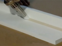
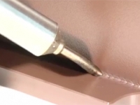
Hot gas welding, also known as hot air welding, is a plastic welding technique which is analogous to metals, though the specific techniques are different. A specially designed heat gun, called a hot air welder, produces a jet of hot air that softens both the parts to be joined and a plastic filler rod, all of which must be of the same or a very similar plastic. Hot air/gas welding is a common fabrication technique for manufacturing smaller items such as chemical tanks, water tanks, heat exchange and plumbing fitting. Two sheets of plastic are heated via a hot gas or a heating element and then rolled together. This is a quick welding process and can be performed continuously.

SPEED TIP WELDING

speed tip welding
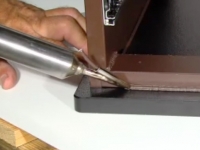
With speed welding, the plastic welder, similar to a soldering iron in appearance and wattage, is fitted with a feed tube for the plastic weld rod. The speed tip heats the rod and the substrate, while at the same time it presses the molten weld rod into position. A bead of softened plastic is laid into the joint, and the parts and weld rod fuse. With some types of plastic such as polypropylene, the melted welding rod must be “mixed” with the semi-melted base material being fabricated or repaired. These welding techniques have been perfected over time and have been utilized for over 50 years by professional plastic fabricators and repairers internationally. Speed tip welding method is a much faster welding technique and with practice can be used in tight corners. A version of the speed tip “gun” is essentially a soldering iron with a broad, flat tip that can be used to melt the weld joint and filler material to create a bond.

PLASTIC WELDED APPLICATIONS INCLUDE:

  • Thermoplastic tanks for plating, anodizing, cleaning, wastewater treatment and chemical processing industries
  • Rotationally Molded Tanks
  • Flexible Drop-in Liners
  • Sinks
  • Sematech approved wet benches
  • One piece construction of cabinets, wet benches, wafer stackers, polishers, spin dryers, and tanks
  • Fume hoods
  • Ducts and fittings for exhaust and ventilation
Partial listing of materials for plastic welding:
  • PVC, CPVC, HDPE,PP, PVDF, LDPE, HDPE.
  • Corzan® FMRC 4910 Listed 3002299.
  • Kytec® (MP-20 resin) Listed 3D1Q5.AM.
  • FR-CP7-D Listed 3D7 Q7.AM.
  • Halar® 901(Ultra pure for DI & UPW systems).
  • Clear Halar® (453) Listed 4D7Q9.AM.
  • Corzan® 11 Listed 3010025.
  • Opaque Halar®.
  • FM4910 approved materials specified for use in the semiconductor and clean room industries

Production Process of PTFE

Tetrafluoroethylene was first prepared in 1933. The current commercial synthesis are based on fluorspar, sulphuric acid and chloroform.
Production Process of PTFE
Basic Production Process of PTFE Polymer:
The Manufacturing of PTFE Polymer/ Resin is basically carried out in two stages. First, TFE Monomer is generally manufactured by synthesis of Calcium Fluoride (Fluorospar), Sulphuric Acid & Chloroform & later polymerisation of TFE is carried out in carefully controlled conditions to form PTFE. Due to presence of stable & strong C-F bonds, PTFE molecule possesses outstanding chemical inertness, high heat resistance & remarkable electrical insulation characteristics; in addition to excellent frictional properties.
Purification of TFE:
Pure monomer is required for polymerisation. If impurities are present it will affect the final product. The gas is first scrubbed to remove any hydrochloric acid and then distilled to separate other impurities.
Polymerisation of TFE:
Pure uninhibited Tetrafluoroethylene can polymerise with violence, even at temperatures initially below that of room temperature. A silver-plated reactor, quarter-filled with a solution consisting of 0.2 parts ammonium persulphate, 1.5 parts borax and 100 parts of water, and with a pH of 9.2. The reactor was closed; evacuated and 30 parts of monomer were let in. The reactor was agitated for one hour at 80°C and after cooling gave an 86% yield of polymer.
PTFE is made commercially by two major processes, one leading to the so called 'granular' polymer and the second leading to a dispersion of polymer of much finer particle size and lower molecular weight. One method of producing the latter involved the use of a 0.1°% aqueous disuccinic acid peroxide solution. The reactions were carried out at temperature up to 90°C.
Another Methods :
Decomposition of TFE under the influence of an electric arc.
Polymerisation carried out by emulsion method using peroxide initiators e.g. H2O2 (Hydrogen peroxide) and ferrous sulphate. In some cases oxygen is used as initiator.
Structure and Properties of PTFE:
The chemical structure of PTFE is linear polymer of C– F2 – C– F2 without any branch & the outstanding properties of PTFE are associated strong & stable Carbon – Fluorine bond.
Polytetrafluoroethylene is a linear polymer free from any significant amount of branching. Whereas the molecule of polyethylene is in the form of a planar zigzag in the crystalline zone this is sterically impossible with that of PTFE due to the fluorine atoms being larger than those of hydrogen. As a consequence the molecule takes up a twisted zigzag with the fluorine atoms packing tightly in a spiral around the carbon-carbon skeleton. A complete turn of the spiral will involve over 26 carbon atoms below 19°C and 30°C above it there being a transition point involving a 1% volume change at this temperature. The compact interlocking of the fluorine atoms leads to a molecule of great stiffness and it is this feature which leads to the high crystalline melting point and thermal form stability of the polymer.
The intermolecular attraction between PTFE molecules is very small, the computed solubility parameter being 12.6 (MJ/m3)1/2The polymer in bulk does not thus have the high rigidity and tensile strength which is often associated with polymers with a high softening point. The carbon-fluorine bond is very stable. Further, where two fluorine atoms are attached to a single carbon atom there is a reduction in the C–F bond distance from 1.42 A to 1.35 A. As a result bond strengths may be as high as 504 kJ/mole. Since the only other bond present is the stable C–C bond, PTFE has a very high heat stability, even when heated above its crystalline melting point of 327°C. Because of its high crystallinity and incapability of specific interaction, there are no solvents at room temperature. At temperatures approaching the melting point certain fluorinated liquids such as per-fluorinated kerosene will dissolve the polymer.
The properties of PTFE are dependent on the type of polymer and the method of processing. The polymer may differ in particle size and/or molecular weight. The particle size will influence case of processing and the quantity of voids in the finished product whilst the molecular weight will influence crystallinity and hence many physical properties. The processing techniques will also affect both crystallinity and void content.
The weight average molecular weights of commercial polymers appear to be very high and are in the range 400000 to 9000000. ICI report that their materials have a molecular weight in the range 500000 to 5000000 and percentage crystallinity greater than 94~ as manufactured. Fabricated parts are less crystalline. The degree of crystallinity of the finished product will depend on the rate of cooling from the processing temperatures. Slow cooling will lead to high crystallinity with fast cooling giving the opposite effect. Low molecular weight materials will also be more crystalline.
It is observed that the dispersion polymer, which is of finer particle size and lower molecular weight, gives products with a vastly improved resistance to flexing and also distinctly higher tensile strengths. These improvements appear to arise through the formation of fiber-like structures in the mass of polymer during processing.

Fluoropolymer Tubing

Fluoropolymer Tubing with its unique combination of chemical, physical, and electrical properties, is used in aerospace, automotive, electronics, chemical manufacturing, healthcare, and food processing. Virtually total chemical inertness, plus heat resistance and excellent dielectric stability, give Fluoropolymer & Kynar ® tubing extended life, superior performance, extremely high reliability, and virtually unmatched versatility in many applications.

Fluoropolymer Tubing

Thin-Wall Transparent Fluoropolymer FEP Tubing

Thin-wall transparent fluoropolymer FEP tubing is manufactured from special virgin grade DuPont thermoplastic FEP fluoropolymer. Unlike PTFE tubing, this material can be heat sealed.

PTFE Tubing

The recommended choice for temperature requirements ranging up to 500º F (260º C), It resists “melt-off” by soldering irons when making terminations.

PVDF Tubing

An abrasion resistant fluoropolymer suitable for use in applications requiring chemical resistance with low permeability. It provides excellent chemical resistance.

PFA Tubing

Offers excellent crack and stress resistance.The product of choice for applications involving extreme chemical resistance combined with high temperature exposure.

FEP Tubing

The preferred material in production of small diameter tubing of continuous lengths. Its chemical and dielectric properties are similar to those of PTFE.

Fluoropolymer Tubing Applications:

Aerospace &Transportation Technology, Electronics, Components & Insulators, Chemical & Pharmaceutical Manufacturing, Food Processing, Environmental Sciences, Air Sampling, Fluid Transfer Devices and Water Processing Systems

PTFE Tubing, PVDF Tubing, PFA Tubing, FEP Tubing and various other fluoropolymer products have great chemical inertness and offer superior mechanical and physical properties.

Teflon® & Non-Stick Coatings

Teflon non-stick industrial coatings are available in both liquid and powder. The versatility of Teflon® coatings allow almost unlimited application to a wide variety of parts sizes and configurations, always adding value far beyond the inherent nonstick qualities. Versatility unmatched by any other engineered material. Industrial Teflon® coatings spray on like paint and bake to a tough, inert finish. Over the years, technology has extended the family of non-stick coatings to ensure a finish with the ideal combination of properties to meet most design needs. In 2015 the United States accounted for 15.5% of the world consumption of PTFE coatings. From 2015 to 2020, US consumption of PTFE coatings is expected to grow at 2.0% per year.


By combining heat resistance with almost total chemical inertness, excellent dielectric stability and a low coefficient of friction, non-stick industrial coatings offer a balance of properties unbeatable by any other material. With an industrial Teflon® coating, the coefficient of friction is generally lowered to a range of 0.02 to 0.15, depending on the load, sliding speed, and type of coating used. Dry lubricant coatings are special versions of Dupont Teflon®-S technology designed to provide lubrication under high-pressure/velocity (PV) conditions. These products are solvent-based, one-coat systems that are usually cured between 148°C/300°F and 371°C/700°F.

Teflon® coating services can be applied to carbon steel, aluminum, stainless steel, steel alloys, brass and magnesium as well as non-metallics such as glass, fiberglass, some rubber and plastics. Optimum adhesion is obtained by roughening the surface before applying the industrial coating.

Teflon® is a registered trademark of Chemours. Orion Industries, Ltd is a Licensed Industrial Applicator of Teflon®.