Vacuum Sintering Furnace Maintenance

Vacuum sintering furnace has been used for a long time,There will be some impurities left in the furnace. We need regular maintenance to avoid damage to the equipment.

  1. when the vacuum sintering furnace is deactivated, the vacuum condition in the furnace should be kept below 6.65*104pa.
  2. The dust cleaning furnace with ethanol or gasoline, moistened with silk, and dry.
  3. the vacuum system or sealing structure and other parts of the equipment should be cleaned with ethanol or gasoline, and coated with vacuum grease after drying, and then assembled.
  4. shell to avoid cleaning regularly, keep clean.
  5. the workpiece, car, material frame, workpiece and so on, after cleaning, and then put into the furnace, to prevent moisture, impurities into.
  6. when the transmission card, to limit and control the phenomenon of failure, should be immediately removed, to avoid forced operation, to avoid damage to equipment.
  7. drive parts should be regular refueling or oil change.
  8. vacuum pumps, valves, measuring instruments, thermal instruments and electrical components and other accessories, should be strictly in accordance with the instructions for use, maintenance and maintenance.
  9. in the maintenance of vacuum sintering furnace, in the case of power failure, and if in the case of live maintenance, it is necessary to ensure the safety of maintenance personnel and equipment.
Sintering Furnace
 

PTFE Manual Press Molding machine exported to Malaysia

 
We are providing our customers with the advantages of high output and low energy consumption, SUNKOO has successfully opened its market to USA, UAE, Korea, India, Russia, Malaysia, etc and attained good reputation among customers.
The machine has passed all the basic and necessary test before shipment to Malaysia. Our technical skillful staff check the machine thoroughly for all the machine before dispatching to shipment. The testing report sent to customer for satisfaction.
 
Manual molding press machine Sunkoo HM400T:
The machine production has capacity for tube is 150 pieces/hour and for rod is 300 pieces/hour.
400T-Platform1000*1000 , 8KW powder.380V3P50Hz.
Max mould height is 700 mm.The effictive travel of ram is 400mm. Down-up press for PTFE. cylinder diameter 500mm. Inside frame 1100*1000.
Moulds for PHM400T finished size:
a.    645 x 755 x 100 mm
b.    545 x 655 x 100 mm
c.    445 x 555 x 100 mm
d.    345 x 455 x 100 mm 
 
Customer Comments for Us:
“I remembered the time when I contacted with the Sunkoo Team, the team has very good communicational skills among its customers to satisfy the actual need. They provide me all the basic details and description about the manual press molding machine. The prices offered was really competitive as compared to market. Finally I am glad to have a manual molding machine. The output is high and much efficient as compared to other machine I have. The technical staff was very skillful and has expertise in their fields. “
What other customers think about us:
ü  I like its Special design for PTFE mold tube and rod. With Manual and Auto two different type operation.
ü  Sunkoo molding machine set up different press power level for high density. The output quality is very good.
ü  As a regular operator of  PTFE moldingmachine , the machine provided by Sunkoo has improved machine based design and efficiency stability over the current machine on the market. It can be used to mold all kinds of PTFE products. Work pressure can be adjusted within rated pressure.
ü  The good thing I found in the machine is, it has the independent electrical and hydraulic system, beside this  it has the adjustment, manual and semiautomatic operating methods and constant process and pressure.
ü  I am happy to have this machine, the price is very reasonable and affordable. I’ll recommend to other manufacturer as well try once you’ll get much profit easily.
 
CONTACT US:
PTFE Factory:No.8 Lvshu 3 road, Xuejia, Xinbei District,Changzhou, Jiangsu,China.213000.
Call us/Whatsapp:+86-13861180959
Skype:sammy.ljf


Mail: info@sukoptfe.com

Aluminum Extrusions

Extrusion is the process by which long straight metal parts can be produced. The cross-sections that can be produced vary from solid round, rectangular, to L shapes, T shapes. Tubes and many other different types. Extrusion is done by squeezing metal in a closed cavity through a tool, known as a die using either a mechanical or hydraulic press.
Aluminum Extrusions
Extrusion produces compressive and shear forces in the stock. No tensile is produced, which makes high deformation possible without tearing the metal. The cavity in which the raw material is contained is lined with a wear resistant material. This can withstand the high radial loads that are created when the material is pushed the die. 
Extrusions, often minimize the need for secondary machining, but are not of the same dimensional accuracy or surface finish as machined parts. Surface finish for steel is 3um; (125 uin), and Aluminum and Magnesium is 0.8 um (30 uin). However, this process can produce a wide variety of cross-sections that are hard to produce cost-effectively using other methods. Minimum thickness of steel is about 3 mm (0.120 in), whereas Aluminum and Magnesium is about 1mm (0.040 in). Minimum cross sections are 250 mm2 (0.4 in2) for steel and less than that for Aluminum and Magnesium. Minimum corner and fillet radii are 0.4 mm (0.015 in) for Aluminum and Magnesium, and for steel, the minimum corner radius is 0.8mm(0.030 in) and 4 mm (0.120 in) fillet radius.
Cold Extrusion: Cold extrusion is the process done at room temperature or slightly elevated temperatures. This process can be used for most materials-subject to designing robust enough tooling that can withstand the stresses created by extrusion. Examples of the metals that can be extruded are lead, tin, aluminum alloys, copper, titanium, molybdenum, vanadium, steel. Examples of parts that are cold extruded are collapsible tubes, aluminum cans, cylinders, gear blanks. The advantages of cold extrusion are:
  • * No oxidation takes place
  • Good mechanical properties due to severe cold working as long as the temperatures created are below the re-crystallization temperature
  • Good surface finish with the use of proper lubricants
Hot Extrusion: Hot extrusion is done at fairly high temperatures, approximately 50 to 75 % of the melting point of the metal. The pressures can range from 35-700 MPa (5076 – 101,525 psi). Due to the high temperatures and pressures and its detrimental effect on the die life as well as other components, good lubrication is necessary. Oil and graphite work at lower temperatures, whereas at higher temperatures glass powder is used.
Typical parts produced by extrusions are trim parts used in automotive and construction applications, window frame members, railings, aircraft structural parts.

Rotational Molding

Rotational molding uses gravity inside a rotating mold to achieve a hollow form. Also called rotomolding, it is an alternative to blow molding for making large, hollow shapes. It is used principally for thermoplastic polymers, but applications for thermosets and elastomers are becoming more common. Rotomolding tends to favor more complex external geometries, larger parts, and lower production quantities than blow molding. The process consists of the following steps: (1) A predetermined amount of polymer powder is loaded into the cavity of a split mold. (2) The mold is then heated and simultaneously rotated on two perpendicular axes, so that the powder impinges on all internal surfaces of the mold, gradually forming a fused layer of uniform thickness. (3) While still rotating, the mold is cooled so that the plastic skin solidifies. (4) The mold is opened, and the part is unloaded. Rotational speeds used in the process are relatively slow. It is gravity, not centrifugal force, that causes uniform coating of the mold surfaces.


Molds in rotational molding are simple and inexpensive compared to injection molding or blow molding, but the production cycle is much longer, lasting perhaps ten minutes or more. To balance these advantages and disadvantages in production, rotational molding is often performed on a multicavity indexing machine, such as the three-station machine shown below The machine is designed so that three molds are indexed in sequence through three workstations. Thus, all three molds are working simultaneously. The first workstation is an unload-load station where the finished part is unloaded from the mold, and the powder for the next part is loaded into the cavity. The second station consists of a heating chamber where hot-air convection heats the mold while it is simultaneously rotated. Temperatures inside the chamber are around 3750C(7000F), depending on the polymer and the item being molded. The third station cools the mold, using forced cold air or water spray, to cool and solidify the plastic molding inside.


A fascinating variety of articles are made by rotational molding. The list includes hollow toys such as hobby horses and playing balls; boat and canoe hulls, sandboxes, small swimming pools; buoys and other flotation devices; truck body parts, automotive dashboards, fuel tanks; luggage pieces, furniture, garbage cans; fashion mannequins; large industrial barrels, containers, and storage tanks; portable outhouses, and septic tanks. The most popular molding material is polyethylene, especially HDPE. Other plastics include polypropylene, ABS, and high-impact polystyrene.

Injection Molding Machines

Injection molding machines differ in both injection unit and clamping unit. The name of the injection molding machine is generally based on the type of injection unit used.
Injection Units. Two types of injection units are widely used today. The reciprocating-screw machine is the most common. This design uses the same barrel for melting and injection of plastic. The alternative unit involves the use of separate barrels for plasticizing and injecting the polymer. This type is called a screw-preplasticizer machine or two-stage machine. Plastic pellets are fed from a hopper into the first stage, which uses a screw to drive the polymer forward and melt it. This barrel feeds a second barrel, which uses a plunger to inject the melt into the mold. Older machines used one plunger-driven barrel to melt and inject the plastic. These machines are referred to as plunger-type injection molding machines.
injectionMolded7
Two alternative injection systems to the reciprocating screw: (a) screw preplasticizer, and (b) plunger type
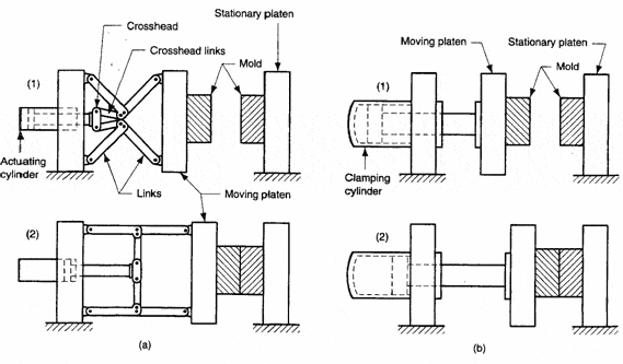
Clamping Units. Clamping designs are of three types: toggle, hydraulic, and hydromechanical. Toggle clamps include various designs. An actuator moves the crosshead forward, extending the toggle links to push the moving platen toward a closed position. At the beginning of the movement, mechanical advantage is low and speed is high; but near the end of the stroke, the reverse is true. Thus, toggle clamps provide both high speed and high force at different points in the cycle when they are desirable. They are actuated either by hydraulic cylinders or ball screws driven by electric motors. Toggle-clamp units seem most suited to relatively low-tonnage machines.
Two clamping designs: (a) one possible toggle clamp design (1) open and (2) closed; and (b) hydraulic clamping (1) open and (2) closed. Tie rods used to guide movuing platens not shown.
injectionMolded8
Hydraulic clamps are used on higher-tonnage injection-molding machines, typically in the range 1300 to 8900 kN (150 to 1000 tons). These units are also more flexible than toggle clamps in terms of setting the tonnage at given positions during the stroke. Hydromechanical clamps are designed for large tonnages, usually above 8900 kN (1000 tons); they operate by (1) using hydraulic cylinders to rapidly move the mold toward closing position, (2) locking the position by mechanical means, and (3) using high pressure hydraulic cylinders to finally close the mold and build tonnage.

Injection Molded Parts

Injection molding is a process in which a polymer is heated to a highly plastic state and forced to flow under high pressure into a mold cavity, where it solidifies. The molded part, called a molding, is then removed from the cavity. The process produces discrete components that are almost always net shape. The production cycle time is typically in the range 10 to 30 seconds, although cycles of one minute or longer are not uncommon. Also, the mold may contain more than one cavity; so that multiple moldings are produced each cycle.
Complex and intricate shapes are possible with injection molding. The challenge in these cases is to design and fabricate a mold whose cavity is the same geometry as the part and which also allows for part removal. Part size can range from about 50 g (2 oz) up to about 25 kg (more than 50 lb), the upper limit represented by components such as refrigerator doors and automobile bumpers. The mold determines the part shape and size and is the special tooling in injection molding. For large complex parts, the mold can cost hundreds of thousands of dollars. For small parts, the mold can be built to contain multiple cavities, also making the mold expensive. Thus, injection molding is economical only for large production quantities.
Injection molding is the most widely used molding process for thermoplastics. Some thermosets and elastomers are injection molded, with modifications in equipment and operating parameters to allow for cross-linking of these materials.

Process and Equipment

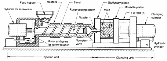
Equipment for injection molding evolved from metal die casting. An injection molding machine consists of two principal components: (1) the plastic injection unit and (2) the mold clamping unit. The injection unit is much like an extruder. It consists of a barrel that is fed from one end by a hopper containing a supply of plastic pellets. Inside the barrel is a screw whose operation surpasses that of an extruder screw in the following respect: in addition to turning for mixing and heating the polymer, it also acts as a ram which rapidly moves forward to inject molten plastic into the mold. A nonreturn valve mounted near the tip of the screw prevents the melt from flowing backward along the screw threads. Later in the molding cycle the ram retracts to its former position. Because of its dual action, it is called a reciprocating screw, which name also identifies the machine type. Older injection molding machines used a simple ram (without screw flights), but the superiority of the reciprocating screw design has led to its widespread adoption in today’s molding plants. To summarize, the functions of the injection unit are to melt and homogenize the polymer, and then inject it into the mold cavity.
The clamping unit is concerned with the operation of the mold. Its functions are to (1) hold the two halves of the mold in proper alignment with each other; (2) keep the mold closed during injection by applying a clamping force sufficient to resist the injection force; and (3) open and close the mold at the appropriate times in the molding cycle. The clamping unit consists of two platens, a fixed platen and a movable platen, and a mechanism for translating the latter. The mechanism is basically a power press that is operated by hydraulic piston or mechanical toggle devices of various types. Clamping forces of several thousand tons are available on large machines.
injectionMolded3
The cycle for injection molding of a thermoplastic polymer proceeds in the following sequence. Let us pick up the action with the mold open and the machine ready to start a new molding: (1) Mold is closed and clamped. (2) A shot of melt, which has been brought to the right temperature and viscosity by heating and by the mechanical working of the screw, is injected under high pressure into the mold cavity. The plastic cools and begins to solidify when it encounters the cold surface of the mold. Ram pressure is maintained to pack additional melt into the cavity to compensate for contraction during cooling. (3) The screw is rotated and retracted with the nonreturn valve open to permit fresh polymer to flow into the forward portion of the barrel. Meanwhile, the polymer in the mold has completely solidified. (4) The mold is opened, and the part is ejected and removed.

Polychlorotrifluoroethylene (PCTFE or PTFCE) Properties & Applications

Polychlorotrifluoroethylene (PCTFE or PTFCE) is a thermoplastic chlorofluoropolymer with the molecular formula (CF2CClF)n, where n is the number of monomer units in the polymer molecule. It is similar to polytetrafluoroethene (PTFE), except that it is a homopolymer of the monomer chlorotrifluoroethylene (CTFE) instead of tetrafluoroethene. It has the lowest water vapor transmission rate of any plastic.
PCTFE
PCTFE has high tensile strength and good thermal characteristics. It is nonflammable and the heat resistance is up to 175 °C.It has a low coefficient of thermal expansion. The glass transition temperature (Tg) is around 45 °C.
PCTFE has one of the highest limiting oxygen index (LOI).It has good chemical resistance. It also exhibits properties like zero moisture absorption and non wetting.
It does not absorb visible light. When subjected to high-energy radiation, it undergoes, like PTFE, degradation.It can be used as a transparent film.
The presence of a chlorine atom, having greater atomic radius than that of fluorine, hinders the close packing possible in PTFE. This results in having a relatively lower melting point among fluoropolymers,around 210–215 °C.
PCTFE is resistant to the attack by most chemicals and oxidizing agents, a property exhibited due to the presence of high fluorine content. However, it swells slightly in halocarbon compounds, ethers, esters and aromatic solvents.PCTFE is resistant to oxidation because it does not have any hydrogen atoms.
PCTFE exhibits a permanent dipole moment due to the molecular asymmetry of its repeating unit. This dipole moment is perpendicular to the carbon-chain axis.
Differences from PTFE
PCTFE is a homopolymer of chlorotrifluoroethylene (CTFE), whereas PTFE is a homopolymer of tetrafluoroethylene. The monomers of the former differs from that of latter structurally by having a chlorine atom replacing one of the fluorine atoms. Hence each repeating unit of PCTFE have a chlorine atom in place of a fluorine atom. This accounts for PCTFE to have less flexibility of chain and hence higher glass transition temperature. PTFE has a higher melting point and is more crystalline than PCTFE, but the latter is stronger and stiffer. Though PCTFE has excellent chemical resistance, it is still less than that of PTFE.PCTFE has lower viscosity, higher tensile strength and creep resistance than PTFE.
PCTFE is injection-moldable and extrudable, whereas PTFE is not.
Applications
PCTFE finds majority of its application due to two main properties: water repulsion and chemical stability. PCTFE films are used as a protective layer against moisture. These include:
  • * moisture barrier in pharmaceutical blister packaging,
  • water-vapour barrier for protecting phosphor coatings in electroluminescent lamps (the phosphor chemicals are sensitive to moisture),
  • protection of liquid-crystal display (LCD) panels, which are sensitive to moisture.
Due to its chemical stability, it acts as a protective barrier against chemicals. It is used as a coating and prefabricated liner for chemical applications. PCTFE is also used for laminating other polymers like PVC, polypropylene, PETG, APET etc. It is also used in transparent eyeglasses, tubes, valves, chemical tank liners, O-rings, seals and gaskets.
PCTFE is used to protect sensitive electronic components because of its excellent electrical resistance and water repulsion. Other uses include flexible printed circuits and insulation of wires and cables.
Low-molecular-weight PCTFE waxes, oils and greases find their application as inert sealants and lubricants. They are also used as gyroscope flotation fluids and plasticizers for thermoplastics.