Screw theory
Screw theory is the algebra and calculus of pairs of vectors, such as forces and moments and angular and linear velocity, that arise in the kinematics and dynamics of rigid bodies. The mathematical framework was developed by Sir Robert Stawell Ball in 1876 for application in kinematics and statics of mechanisms (rigid body mechanics).
Screw theory provides a mathematical formulation for the geometry of lines which is central to rigid body dynamics, where lines form the screw axes of spatial movement and the lines of action of forces. The pair of vectors that form the Plücker coordinates of a line define a unit screw, and general screws are obtained by multiplication by a pair of real numbers and addition of vectors.
An important result of screw theory is that geometric calculations for points using vectors have parallel geometric calculations for lines obtained by replacing vectors with screws. This is termed the transfer principle.
Screw theory has become an important tool in robot mechanics, mechanical design, computational geometry and multibody dynamics. This is in part because of the relationship between screws and dual quaternions which have been used to interpolate rigid-body motions. Based on screw theory, an efficient approach has also been developed for the type synthesis of parallel mechanisms (parallel manipulators or parallel robots).
A spatial displacement of a rigid body can be defined by a rotation about a line and a translation along the same line, called a screw displacement. This is known as Chasles’ theorem. The six parameters that define a screw displacement are the four independent components of the Plücker vector that defines the screw axis, together with the rotation angle about and linear slide along this line, and form a pair of vectors called a screw. For comparison, the six parameters that define a spatial displacement can also be given by three Euler Angles that define the rotation and the three components of the translation vector.
A spatial displacement of a rigid body can be defined by a rotation about a line and a translation along the same line, called a screw displacement. This is known as Chasles’ theorem. The six parameters that define a screw displacement are the four independent components of the Plücker vector that defines the screw axis, together with the rotation angle about and linear slide along this line, and form a pair of vectors called a screw. For comparison, the six parameters that define a spatial displacement can also be given by three Euler Angles that define the rotation and the three components of the translation vector.
A screw is a six-dimensional vector constructed from a pair of three-dimensional vectors, such as forces and torques and linear and angular velocity, that arise in the study of spatial rigid body movement. The components of the screw define the Plücker coordinates of a line in space and the magnitudes of the vector along the line and moment about this line.
Machinist
A machinist is a person who machines using hand tools and machine tools to prototype, fabricate or make modifications to a part that is made of metal, plastics, or wood.
Related occupational titles
A traditional machinist is one who can: operate a machine tool, disassemble and repair the machine tool by building new parts such as gears, splines, and shafts from scratch using various machine tools such as mills, lathes, grinders, planers, etc. Then reassemble the machine tool and operate it.
A traditional machinist is one who can: operate a machine tool, disassemble and repair the machine tool by building new parts such as gears, splines, and shafts from scratch using various machine tools such as mills, lathes, grinders, planers, etc. Then reassemble the machine tool and operate it.
Under the machinist title are other specialty titles that refer to specific skills that may be more highly developed to meet the needs of a particular job position, such as fitter (assembles parts), turning hand, mill hand, and grinder. Some titles reflect further development of machinist skills such as tool and die maker, patternmaker, mold maker, programmer, and operator[disambiguation needed]. Depending on the company, a machinist can be any or all of the titles listed above. A machinist is one who is called on to fix a problem with a part or to create a new one using metal working, plastic, or in some cases, wood.
Role in manufacturing
A machinist is usually called upon when a part needs to be produced from a material by cutting. Such a part may be unique or may be needed in the thousands. This could include a machinery part for a production line or anything that can be made from metal or plastic. Producing a part will often require several steps and more than one machine tool. Each machine tool plays a specific role in cutting away excess material. When large numbers of parts are needed, production planning is required to plan the most logical workflow through a series of machines. Computer numerical controlled (CNC) machines are a special computer-driven tool that can machine a large variety of shapes, and whose use in the workflow depends on the part to be machined.
A machinist is usually called upon when a part needs to be produced from a material by cutting. Such a part may be unique or may be needed in the thousands. This could include a machinery part for a production line or anything that can be made from metal or plastic. Producing a part will often require several steps and more than one machine tool. Each machine tool plays a specific role in cutting away excess material. When large numbers of parts are needed, production planning is required to plan the most logical workflow through a series of machines. Computer numerical controlled (CNC) machines are a special computer-driven tool that can machine a large variety of shapes, and whose use in the workflow depends on the part to be machined.
CNC machines are becoming the standard due to their speed, precision, flexibility, and reduced downtime while changing jobs. Production runs consisting of large numbers of parts are more cost effective and commonly referred to as production work in the trade. Conversely, small production runs are sometimes referred to as prototype or jobbing work.
Production engineers use blueprints and engineering drawings to produce detailed specifications of the part, especially its geometry (shape), then decide on a strategy to make it. Machine tools are then configured by the machinist or toolset and production commences. The machinist works with the quality department to ensure the specifications are maintained in the finished product.
Large commercial organizations often staff machinists on site in a maintenance mode to ensure continuing operations of the production machinery. The labor cost for this role is significantly lower than costs involved with production shutdowns.
Source:http://ptfe-machinery.com/machinist/
Source:http://ptfe-machinery.com/machinist/
Skiving machine

Skiving or scarfing machines cut material off in slices, usually metal, but also leather or laminates. The process is used instead of rolling the material to shape when the material must not be work hardened, or must not shed minute slivers of metal later which is common in cold rolling processes.
The skiving process, meaning “to slice”, can be applied to a variety of applications and materials. In leather, skiving knives trim the thickness of the leather, often around the edges, to thin the material and make it easier to work with. In metal working, skiving can be used to remove a thin dimension of material or to create thin slices in an existing material, such as heat sinks where a large amount of surface area is required relative to the volume of the piece of metal.
The process involves moving the strip past precision-profiled slotted tools made to an exact shape, or past plain cutting tools. The tools are all usually made of tungsten carbide-based compounds. In early machines, it was necessary to precisely position the strip relative to the cutting tools, but newer machines use a floating suspension technology which enables tools to locate by material contact. This allows mutual initial positioning differences up to approximately 12 mm (0.47 in) followed by resilient automatic engagement. Products using this technology directly are automotive seatbelt springs, large power transformer winding strip, rotogravure plates, cable and hose clamps, gas tank straps, and window counterbalance springs. Products using the process indirectly are tubes and pipe mills where the edge of the strip is accurately beveled prior to being folded into tubular form and seam welded. The finished edges enable pinhole free welds.
For lines which use low speed welding processes, such as laser welding, the skiving tools cannot normally cut – for example at speeds below metal planing speeds or about 10 meters/minute (33 feet/minute). In these cases the tools can be vibrated at high frequency to artificially increase the relative speed between the tools and strip.
Another metal skiving application is for hydraulic cylinders, where a round and smooth cylinder inside is required for proper actuation. Several skiving knives on a round tool pass through a bore to create a perfectly round hole. Often, a second operation of roller burnishing follows to cold-work the surface for mirror-finish. This process is common among manufacturers of hydraulic and pneumatic cylinders.
Skiving can be applied to gear cutting, where internal gears are skived with a rotary cutter (rather than shaped or broached) in a process analogous to the hobbing of external gears.
Skiving is also used for the manufacturing of heat sinks for PC cooling products. A PC cooler created with the use of skiving has the benefit that the heat sink base and the heat sink fins are created from one piece of material (copper or aluminum). This provides optimal dissipation and transfer of the heat from the base to the fins. Additionally, the skiving process also increases the roughness of the heat-sink’s fins. Unlike the underside of a heat-sink which needs to be smooth for maximum surface area contact with the heat-source that it cools, the fins benefit from this roughness because it increases the fins’ surface area which serves to provide more area on which to release heat into the ambient environment.
Thermoforming Engineering & Type
Thermoforming has benefited from applications of engineering technology, although the basic forming process is very similar to what was invented many years ago. Microprocessor and computer controls on more modern machinery allow for greatly increased process control and repeatability of same-job setups from one production run with the ability to save oven heater and process timing settings between jobs. The ability to place formed sheet into an inline trim station for more precise trim registration has been hugely improved due to the common use of electric servo motors for chain indexing versus air cylinders, gear racks, and clutches on older machines. Electric servo motors are also used on some modern and more sophisticated forming machines for actuation of the machine platens where form and trim tooling are mounted, rather than air cylinders which have traditionally been the industry standard, giving more precise control over closing and opening speeds and timing of the tooling. Quartz and radiant-panel oven heaters generally provide more precise and thorough sheet heating over older cal-rod type heaters, and better allow for zoning of ovens into areas of adjustable heat..
A new technology, ToolVu, has been developed to provide real-time feedback on thermoformer machines. This stand-alone system connects directly to the thermoformer and utilizes multiple sensors to record production-run data in real time including air pressure, temperature, tool strain gauge and other specifications. The system sends out multiple warnings and alerts whenever pre-set production parameters are compromised during a run. This reduces machine down time, lowers startup time and decreases startup scrap.
An integral part of the thermoforming process is the tooling, which is specific to each part that is to be produced. Thin-gauge thermoforming as described above is almost always performed on in-line machines and typically requires molds, plug assists, pressure boxes and all mounting plates as well as the trim tooling and stacker parts that pertain to the job. Thick or heavy-gauge thermoforming also requires tooling specific to each part, but because the part size can be very large, the molds can be cast aluminum or some other composite material as well as machined aluminum as in thin gauge. Typically, thick-gauge parts must be trimmed on CNC routers or hand trimmed using saws or hand routers. Even the most sophisticated thermoforming machine is limited to the quality of the tooling. Some large thermoforming manufacturers choose to have design and tool making facilities in house while others will rely on outside tool-making shops to build the tooling.
Plastic Processing Type
Type:injection moulding, plastics extrusion, stretch-blow molding, thermoforming, compression molding, calendering, transfer molding, laminating, fiberglass molding, pultrusion, filament winding, vacuum forming, rotational molding
Injection moulding
Injection moulding BrE or Injection molding AmE, is a manufacturing process for producing parts by injecting molten material into a mould. Injection moulding can be performed with a host of materials mainly including metals, (for which the process is called die-casting), glasses, elastomers, confections, and most commonly thermoplastic and thermosetting polymers. Material for the part is fed into a heated barrel, mixed (Using a helical shaped screw), and injected (Forced) into a mould cavity, where it cools and hardens to the configuration of the cavity:240 After a product is designed, usually by an industrial designer or an engineer, moulds are made by a mould-maker (or toolmaker) from metal, usually either steel or aluminium, and precision-machined to form the features of the desired part. Injection moulding is widely used for manufacturing a variety of parts, from the smallest components to entire body panels of cars. Advances in 3D printing technology, using photopolymers which do not melt during the injection moulding of some lower temperature thermoplastics, can be used for some simple injection moulds.
Parts to be injection moulded must be very carefully designed to facilitate the moulding process; the material used for the part, the desired shape and features of the part, the material of the mould, and the properties of the moulding machine must all be taken into account. The versatility of injection moulding is facilitated by this breadth of design considerations and possibilities.
Plastics extrusion
Plastics extrusion is a high-volume manufacturing process in which raw plastic is melted and formed into a continuous profile. Extrusion produces items such as pipe/tubing, weatherstripping, fencing, deck railings, window frames, plastic films and sheeting, thermoplastic coatings, and wire insulation.
This process starts by feeding plastic material (pellets, granules, flakes or powders) from a hopper into the barrel of the extruder. The material is gradually melted by the mechanical energy generated by turning screws and by heaters arranged along the barrel. The molten polymer is then forced into a die, which shapes the polymer into a shape that hardens during cooling.
Stretch-blow molding
Blow molding ( BrE molding ) is a manufacturing process by which hollow plastic parts are formed: It is also used for forming glass bottles. In general, there are three main types of blow molding: extrusion blow molding, injection blow molding, and injection stretch blow molding. The blow molding process begins with melting down the plastic and forming it into a parison or in the case of injection and injection stretch blow moulding (ISB) a preform. The parison is a tube-like piece of plastic with a hole in one end through which compressed air can pass.
The parison is then clamped into a mold and air is blown into it. The air pressure then pushes the plastic out to match the mold. Once the plastic has cooled and hardened the mold opens up and the part is ejected . The cost of blow moulded parts is higher than that of injection – moulded parts but lower than rotational moulded parts
Thermoforming
Thermoforming is a manufacturing process where a plastic sheet is heated to a pliable forming temperature, formed to a specific shape in a mold, and trimmed to create a usable product. The sheet, or “film” when referring to thinner gauges and certain material types, is heated in an oven to a high-enough temperature that permits it to be stretched into or onto a mold and cooled to a finished shape. Its simplified version is vacuum forming.
Compression molding
Compression Molding is a method of molding in which the moulding material, generally preheated, is first placed in an open, heated mould cavity. The mold is closed with a top force or plug member, pressure is applied to force the material into contact with all mold areas, while heat and pressure are maintained until the molding material has cured. The process employs thermosetting resins in a partially cured stage, either in the form of granules, putty-like masses, or preforms.
Calendering
Calendering is a finishing process used on cloth, paper, or plastic film. A calender is employed, usually to smooth, coat, or thin a material.
With textiles, fabric is passed under rollers at high temperatures and pressures. Calendering is used on fabrics such as moire to produce its watered effect and also on cambric and some types of sateens.
In preparation for calendering, the fabric is folded lengthwise with the front side, or face, inside, and stitched together along the edges.The fabric can be folded together at full width, however this is not done as often as it is more difficult.
The fabric is then run through rollers that polish the surface and make the fabric smoother and more lustrous. High temperatures and pressure are used as well. Fabrics that go through the calendering process feel thin, glossy and papery.
Transfer molding
Transfer molding
Transfer molding (BrE moulding) is a manufacturing process where casting material is forced into a mold. Transfer molding is different from compression molding in that the mold is enclosed rather than open to the fill plunger resulting in higher dimensional tolerances and less environmental impact. Compared to injection molding, transfer molding uses higher pressures to uniformly fill the mold cavity. This allows thicker reinforcing fiber matrices to be more completely saturated by resin. Furthermore, unlike injection molding the transfer mold casting material may start the process as a solid. This can reduce equipment costs and time dependency. The transfer process may have a slower fill rate than an equivalent injection molding processes.
Laminating
Lamination is the technique of manufacturing a material in multiple layers, so that the composite material achieves improved strength, stability, sound insulation, appearance or other properties from the use of differing materials. A laminate is a permanently assembled object by heat, pressure, welding, or adhesives.
Fiberglass molding
Fiberglass molding is a process in which fiberglass reinforced resin plastics are formed into useful shapes.
The process usually involves first making a mold and then using the mold to make the fiberglass component.
Pultrusion
Pultrusion is a continuous process for manufacture of composite materials with constant cross-section. The term is a portmanteau word, combining “pull” and “extrusion”. As opposed to extrusion, which pushes the material, pultrusion works by pulling the material.
Filament winding
Filament winding is a fabrication technique mainly used for manufacturing open (cylinders) or closed end structures (pressure vessels or tanks). This process involves winding filaments under tension over a rotating mandrel. The mandrel rotates around the spindle (Axis 1 or X: Spindle) while a delivery eye on a carriage (Axis 2 or Y: Horizontal) traverses horizontally in line with the axis of the rotating mandrel, laying down fibers in the desired pattern or angle. The most common filaments are glass or carbon and are impregnated in a bath with resin as they are wound onto the mandrel. Once the mandrel is completely covered to the desired thickness, the resin is cured. Depending on the resin system and its cure characteristics, often the rotating mandrel is placed in an oven or placed under radiant heaters until the part is cured. Once the resin has cured, the mandrel is removed or extracted, leaving the hollow final product. For some products such as gas bottles, the ‘mandrel’ is a permanent part of the finished product forming a liner to prevent gas leakage or as a barrier to protect the composite from the fluid to be stored.
Vacuum forming
Vacuum forming is a simplified version of thermoforming, where a sheet of plastic is heated to a forming temperature, stretched onto a single-surface mold, and forced against the mold by a vacuum. This process can be used to form plastic into permanent objects such as turnpike signs and protective covers. Normally draft angles are present in the design of the mold (a recommended minimum of 3°) to ease removal of the formed plastic part from the mold.
Rotational molding
Rotational Molding (BrE moulding) involves a heated hollow mold which is filled with a charge or shot weight of material. It is then slowly rotated (usually around two perpendicular axes), causing the softened material to disperse and stick to the walls of the mold. In order to maintain even thickness throughout the part, the mold continues to rotate at all times during the heating phase and to avoid sagging or deformation also during the cooling phase. The process was applied to plastics in the 1940s but in the early years was little used because it was a slow process restricted to a small number of plastics. Over the past two decades, improvements in process control and developments with plastic powders have resulted in a significant increase in usage.
7 fillers to enhance the performance of virgin PTFE sealing
PTFE (Polytetrafluoroethylene) has become a commonly used material in sealing applications where other materials do not meet temperature, chemical compatibility, friction, or wear requirements. Many users are unaware that “fillers” may be added to PTFE in order to enhance certain characteristics not found in virgin PTFE. Virgin PTFE possesses “creep” behavior that may reduce effectiveness in mechanical applications.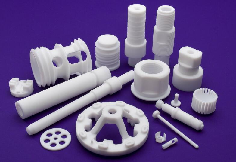
Significant deformation of virgin PTFE may occur over time even at room temperatures. The use of fillers improves the physical attributes of virgin PTFE, including creep and wear resistance. Which filler to use certainly depends on the application. Some of the common fillers include:
1,Glass is the most common filler for PTFE. Widely used in hydraulic piston rings, glass gives good wear resistance, low creep, and good compressive strength. Glass also has excellent chemical compatibility. The percentage of glass varies between 5 percent and 40 percent. The major disadvantage is that glass-filled PTFE compounds are abrasive to mating surfaces, especially in rotary applications.
2,Molybdenum disulfide (MoS2) improves wear resistance and further lowers the coefficient of friction. “Moly” is typically combined with other fillers (such as glass and bronze).
3,Carbon imparts excellent compression (low deformation under load) and wear resistance, good thermal conductivity, and low permeability. Carbon-filled PTFE compounds are not as abrasive as glass-filled compounds, but they are still more abrasive than polymer-filled compounds. The percentage of carbon added varies between 5 percent and 15 percent. Carbon-filled compounds have excellent wear and friction properties when combined with graphite. Carbon fiber lends better creep resistance than carbon powder, but fiber is more expensive.
4,Graphite is a crystal modification of high-purity carbon. Its flaky structure imparts excellent lubricity and decreased wear. Percentages of this filler vary between 5 percent and 15 percent. Graphite is often combined with other fillers (especially carbon and glass).
5,Bronze lends excellent wear resistance and thermal conductivity. Bronze-filled materials have higher friction than other filled PTFE compounds, but that can be improved by adding moly or graphite. Bearing and piston ring applications often use compounds containing 55 percent bronze – 5 percent moly. Bronze-filled compounds have poorer chemical resistance than other PTFE compounds. Bronze, when used as a filler, is added in percentages of weight between 40 percent and 60 percent.
6,Ekonol is thermally stable aromatic polyester. When blended with PTFE, it produces a composite material with excellent high temperature and wear resistance. Ekonol will not wear mating metal surfaces, making it good for rotary applications. Ekonol-filled materials are also good for food service.
7,Polyimide is another type of polymeric filler, which offers superior wear and abrasion resistance. Polyimide-filled PTFE compounds have about the lowest friction properties of all filled PTFE materials, so they provide great performance in non-lubricated (dry) applications. They will not abrade mating surfaces (even soft materials such as brass, stainless steel, aluminum, and plastic). Polyimide is one of the most expensive PTFE fillers, however.
Basic Types of Plastic Pipes
Solid wall pipe
Extruded pipes consisting of one layer of a homogeneous matrix of thermoplastic material which is ready for use in a pipeline.
Structured wall pipe
Structured-wall pipes and fittings are products which have an optimized design with regard to material usage to achieve the physical, mechanical and performance requirements.
Structured Wall Pipes are tailor made solutions of piping systems, for a variety of applications and in most cases developed in cooperation with users.
Barrier pipe
Pipe incorporating a flexible metallic layer as the middle of three bonded layers. Barrier pipe is used, for example, to provide additional protection for the contents passing through the pipe (particularly drinking water) from aggressive chemicals or other pollution when laid in ground contaminated by previous use.
Most plastic pipe systems are made from thermoplastic materials. The production method involves melting the material, shaping and then cooling. Pipes are normally produced by extrusion.
Pipe Extrusion
Pipes made from PVC, PE and PP and other thermoplastics are usually manufactured by extrusion. This process starts by feeding plastic material (pellets, granules, flakes or powders) from a hopper into the barrel of the extruder.
The material is gradually melted by the mechanical energy generated by turning screws and by heaters arranged along the barrel.
The molten polymer is then forced into a die, which shapes the polymer into a pipe that hardens during cooling.
The material is gradually melted by the mechanical energy generated by turning screws and by heaters arranged along the barrel.
The molten polymer is then forced into a die, which shapes the polymer into a pipe that hardens during cooling.
A great advantage of extrusion is that pipes can be made to any length. Due to its flexibility, pipes can be made at long lengths even coiling on a reel. Another advantage is the extrusion of pipes with integrated coupler including rubber seal.
Jointing
Pipes can be connected in a variety of ways to form reliable and leak-free pipe systems. They can be connected by either a push fit joint with rubber seal or by a solvent cement system or by welding.
Straight pipes are mostly connected by pushing the plain end of one pipe into the socketed end of another. This technology is mainly used by PVC and PP piping systems. A variety of fittings are available to make branches or bends or to connect the pipe to other materials.
PE pipes for water pressure and gas distribution can also be connected by welding systems. Two pocesses are mostly used: Butt welding to connect pipe to pipe ends, and electro welding of fittings containing a heating wire to allow melting of materials together. A variety of fittings are available. Welding systems have proven to be very reliable.
Injection Moulding
Fittings such as joints, elbows or T-pieces are usually produced by injection-moulding.
In injection-moulding, the plastic material is fed from a hopper into the melting section of the injection-moulding machine. After melting, the material is transported forward by the screw and homogenised before being injected into the mould to form the shape of the desired product. In the cooling step, the plastic solidifies. Then the mould is opened and the product is ejected.
Blow Moulding
In the blow moulding process, the plastic is melted and extruded into a hollow tube that is then captured by closing it into a cooled metal mould. Air is then blown into the tube – inflating it into the desired shape. After the plastic has cooled sufficiently, the mould is then opened and the part is ejected.
Inspection chambers, manholes, septic and storage tanks are some of the products manufactured by this technique. Typically, these products are much lighter and easier to handle than non plastic materials.
Rotational Moulding
The rotational moulding process is a high temperature, low pressure plastic forming method that uses biaxial rotation to produce hollow, one piece parts. In the plastic pipe industry, it is typically used to make large inspection chambers, water and septic tanks from polyethylene (PE) or polypropylene (PP).