Plastic Extrusion Basic Information – Supplies & Process & Design
Whether it’s one hundred yards of pipe-tubing or a thousand Crazy Straws, plastic extrusion is in frequent use in today’s plastics industry because it’s readily available and easy to work with. The plastic extrusion process involves melting plastic material, forcing it into a die to shape it into a continuous profile, and then cutting it to length. The process is a good choice for applications that require a final product with a constant cross-section. The low cost and high production rates make it a common manufacturing choice for products such as piping, plastic sheeting, weather stripping, wire insulation and adhesive tape.
Plastic Extrusion Supplies
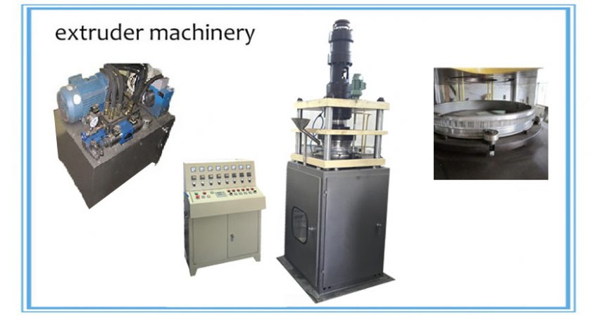
Prior to beginning the plastic extrusion process, the proper machinery and supplies must be obtained, specifically a plastic extruder machine. This device is a fairly simple machine that facilitates the extrusion process from start to finish. The main components of a plastic extruder include a hopper, barrel, screw drive and screw drive motor.
The second most important component is the raw thermoplastic material intended for extrusion. The majority of extrusion operations rely on resin plastic (small solid beads) to allow for simple loading and quick melting times. Common plastic materials used in the extrusion process include high impact polystyrene (HIPS), PVC, polyethylene, polypropylene, and ABS.
The final component necessary for plastic extrusion is the die. The die serves as the mold for the plastic—in plastic extrusion, dies allow for even flow of the molten plastic. Dies typically must be custom made and may require additional lead time prior to beginning the manufacturing process.
The Basic Process Of Plastic Extrusion
The plastic extrusion process begins with the placement of raw resin into the extruder’s hopper. If the resin lacks additives necessary for the particular application (such as UV inhibitors, anti-oxidants, or colorants), then they are then added to the hopper. Once in place, the resin is typically gravity-fed through the feed throat of the hopper down into the extruder’s barrel. Within the barrel is a long, rotating screw that feeds the resin forward in the barrel towards the die.
The plastic extrusion process begins with the placement of raw resin into the extruder’s hopper. If the resin lacks additives necessary for the particular application (such as UV inhibitors, anti-oxidants, or colorants), then they are then added to the hopper. Once in place, the resin is typically gravity-fed through the feed throat of the hopper down into the extruder’s barrel. Within the barrel is a long, rotating screw that feeds the resin forward in the barrel towards the die.
As the resin moves along within the barrel, it is subjected to extremely high temperatures until it starts to melt. Depending on the type of thermoplastic, barrel temperatures can range between 400 and 530 degrees Fahrenheit. Most extruder’s have a barrel that gradually increases in heat from the loading end to the feed pipe to enable gradual melting and minimize the possibility of plastic degradation.
Once the molten plastic reaches the end of the barrel, it is forced through a screen pack and fed into the feed pipe that leads to the die. The screen, reinforced by a breaker plate due to high pressures in the barrel, serves to remove contaminants that may be present in the molten plastic. The porosity of the screen, number of screens, and other factors can be manipulated until uniform melting occurs as a result of the right amount of back pressure.
Once in the feed pipe, the molten metal is fed into the die cavity, where it cools and hardens. To expedite the cooling process, the newly formed plastic receives a sealed water bath. In the case of plastic sheeting extrusions, cooling rolls replace the water bath.
Temperature Maintenance
Maintaining the correct temperature level and melting rate of the resin is an important consideration when creating plastic extrusions. Optimal temperature maximizes uniform fluidity of the plastic, and minimizes the possibility for stress and warping of the final product. Variables such as pressure and friction that build up in the barrel of the extruder mean that temperatures are not remaining constant. Heaters must be monitored, lowered, raised, or shutoff as necessary to maintain constant heat within the extruder—cooling fans and cast-in heater jackets can also help maintain proper extrusion temperature.
Maintaining the correct temperature level and melting rate of the resin is an important consideration when creating plastic extrusions. Optimal temperature maximizes uniform fluidity of the plastic, and minimizes the possibility for stress and warping of the final product. Variables such as pressure and friction that build up in the barrel of the extruder mean that temperatures are not remaining constant. Heaters must be monitored, lowered, raised, or shutoff as necessary to maintain constant heat within the extruder—cooling fans and cast-in heater jackets can also help maintain proper extrusion temperature.
Importance Of Screw Design
Since the heating rate, feed rate, and other integral extrusion factors are directly dependent on the only moving part in the plastic extruder—the screw—carefully consideration of the size and design of this component is necessary. Calculation of screw diameter and length is based on the melting rate, size of the resin, type of raw plastic, and amount of pressure required maintaining uniformity. For applications where materials are compounded within the barrel of the extruder, a twin-screw design may be used to enable adequate mixing.
Since the heating rate, feed rate, and other integral extrusion factors are directly dependent on the only moving part in the plastic extruder—the screw—carefully consideration of the size and design of this component is necessary. Calculation of screw diameter and length is based on the melting rate, size of the resin, type of raw plastic, and amount of pressure required maintaining uniformity. For applications where materials are compounded within the barrel of the extruder, a twin-screw design may be used to enable adequate mixing.
Specialty Plastic Extrusion Processes
Many applications call for specialized extrusion processes to obtain adequate results or speed up the production process. Common specialty extrusion processes include:
Many applications call for specialized extrusion processes to obtain adequate results or speed up the production process. Common specialty extrusion processes include:
- Blown film extrusion: Used to fabricate plastic film products such as grocery and food storage bags The dies in this process feature an upright, cylindrical design that pulls the molten plastic upward as it forms and cools.
- Coextrusion: Several layers of material are extruded at the same time. Two or more extruders feed different types of plastic into a single extrusion head.
- Overjacketing: Extrusion is employed to coat an item in protective plastic coating. Exterior wire and cable jacketing is the most common application of overjacketing.
- Tubing extrusion: Similar to traditional extrusion, except the die includes interior pins or mandrels to facilitate the production of hollow plastic materials.
How plastic products are formed?
Discover the basic methods of processing thermoplastic and thermoset materials:
Plastics are ubiquitous, appearing in the most cutting edge technologies as well as in the most mundane items. These polymers—chainlike molecules—are so widely used that their absence would be instantly and profoundly felt. Plastics can be divided into two groups: 1) thermoplastics, which once formed, can be heated and repeatedly reformed, and 2) thermosets, which cannot be remelted once formed. Here are the basic ways that these two groups of plastics are processed:
Plastics are ubiquitous, appearing in the most cutting edge technologies as well as in the most mundane items. These polymers—chainlike molecules—are so widely used that their absence would be instantly and profoundly felt. Plastics can be divided into two groups: 1) thermoplastics, which once formed, can be heated and repeatedly reformed, and 2) thermosets, which cannot be remelted once formed. Here are the basic ways that these two groups of plastics are processed:
Injection Molding
This is the primary method of forming thermoplastics. In injection molding, plastic material gets loaded into a hopper and proceeds into a heated injection unit. A reciprocating screw moves the plastic along this lengthy heating chamber, where the material is melted to a fluid state. When the softened plastic reaches the end of this chamber, it is forced at high pressure through a nozzle and into a cool mold. The plastic is contained within this mold, whose halves are held shut by clamps, until it sets. As soon as the material solidifies, the mold opens, and the press ejects the formed plastic.
Modified versions of this technique are sometimes used to process thermoset materials. But problems can occur because the softened thermosetting plastic can end up hardening while still in the heating chamber. To address this issue, jet molding, offset molding and screw-type machine molding liquefy the thermosetting plastic just as it passes through the injection nozzle into the mold.
Blow Molding
This method is used to form hollow objects out of thermoplastic materials. In blow molding, a molten tube of thermoplastic material is formed, and then compressed air is used to blow up the tube, forcing the material to take the shape of the interior of a chilled blow mold. The most widely used blow molding techniques are extrusion, injection and injection-stretch.
In extrusion blow molding, the plastic material is forced through a die to form the molten plastic tube, which is blown up by compressed air. Meanwhile, injection blow molding involves injection molding a preform—which resembles a test tube—then putting the preform into a blow mold to be filled with compressed air. The third method, injection-stretch blow molding, incorporates the element of stretch before blow forming.
Thermoforming
The process of thermoforming plastic sheet has advanced quickly in recent years. This method involves heating thermoplastic sheet to a compliant plastic state and then using air and/or mechanical assists to make it conform to a mold’s contours.
Air pressure can be anywhere from almost zero to several hundred psi. Up to about 14 psi of atmospheric pressure, the necessary pressure is achieved by vacating the space between the sheet and the mold in order to take advantage of this atmospheric pressure. This is called vacuum forming, a type of thermoforming that will satisfactorily reproduce the mold configuration in most forming applications.
Air pressure can be anywhere from almost zero to several hundred psi. Up to about 14 psi of atmospheric pressure, the necessary pressure is achieved by vacating the space between the sheet and the mold in order to take advantage of this atmospheric pressure. This is called vacuum forming, a type of thermoforming that will satisfactorily reproduce the mold configuration in most forming applications.
Compression Molding
This is the most widely used method of processing thermoset materials. It’s not normally employed to form thermoplastics. Compression molding involves applying heat and pressure on a material in a mold so that it is squeezed into a particular shape.
In this process, plastic molding powder, blended with fillers to enhance the final product’s properties, is placed directly into an open mold cavity. The mold is then shut, applying heat and pressure on the plastic and forcing it to flow throughout the mold. While the heated mold is closed, the thermosetting plastic chemically changes and permanently sets into the mold shape. The three compression molding variables—pressure, temperature and the time the mold is closed—differ with the product design and the material being formed.
Transfer Molding
Like compression molding, this method is used to form thermoset materials and involves permanently curing the plastic in a mold under heat and pressure. Unlike compression molding, however, transfer molding includes heating the plastic to a fluid state before it gets to the mold and forcing it into a closed mold using a hydraulically actuated plunger.
Transfer molding was designed to mold complex objects with small deep holes or many metal inserts. While compression molding relies on a dry mold compound that can disrupt the placement of the metal inserts and pins that form the holes, the plastic material in transfer molding is liquefied so that it can flow around these metal parts without disturbing their position.
Reaction Injection Molding
This processing technique is relatively new but has quickly gained acceptance. In reaction injection molding (RIM), two liquid components—polyols and isocyanates—are blended in a chamber at comparatively low temperatures (75°-140°F) before being injected into a closed mold, where an exothermic reaction takes place. Because of this reaction, this process consumes much less energy than any other injection molding system.
Reinforced RIM (R-RIM) involves adding material such as chopped or milled glass fiber to the polyurethane to improve stiffness and modulus and thereby broaden applications.
Extrusion
This method can form thermoplastic materials into continuous sheeting, film, tubes, rods, profile shapes and filaments. Additionally, this process is used to form thermoplastics into coatings for wire, cable and cord.
In extrusion molding, dry plastic material is first put into a hopper that feeds into a lengthy heating chamber. The plastic material is pushed through this chamber by a continuously revolving screw. Upon reaching the end of the chamber, the molten material is forced out through a tiny opening or die, which bears the shape required in the final product. As the plastic extrusion emerges from the die, it is placed onto a conveyor belt where it is cooled, most commonly by blowers or through water immersion.
Screw Design in Plastic Extrusion
The basic extrusion screw has three distinct parts, each engineered to do a specific task. The feed section is in the rear of the screw, where plastic pellets are gravity fed from above and conveyed forward. The length to diameter ratio of the feed section is typically four or five to one, which is sufficient to build up the pressure needed to transport the plastic. However, the friction between the barrel wall and the plastic must be greater than that between the screw and the plastic in order for lateral movement to occur.

A barrel heater helps the plastic develop tack and stick to a wall. Sometimes, the screw is also chilled to free it of clinging pellets. Feed section length ratios can be increased to eight or ten to one for plastics with a low coefficient of friction. This extra length gives the plastic more time to heat up to a higher temperature, creating more friction at the barrel. From here, the plastic is channeled into the transition section of the screw.
In the transition section, the plastic is transformed into its liquid state through two concurrent methods. Barrel heaters provide some initial melting, while the shear caused by the motion of the plastic against the barrel completes the process. In this stage, the root of the screw increases while the flutes, or “flights,” subsequently decrease in size. This leaves less space for the plastic mass that has been compacted in the feed section. As pressure, shear and friction increases, the plastic begins to melt and flow. The transition section typically occupies five to ten diameters of the cycle.
In the metering or pumping section, the molten plastic is guided into a die. The root diameter of the screw and the size of the flights remain constant in this stage, and its length varies from four to eight diameters, depending on the application.
Barrier Screws
In the transition, or melting, section of a conventional extrusion screw, molten plastic has a tendency to surround the solid pellets, keeping them away from the barrel where melting takes place. This blockage can result in damaged equipment or unusable extrusions. The barrier screw was designed to address this problem, and it has become ubiquitous in the extrusion industry.
Barrier screws have additional flights serving as barriers in the melting section. These barrier flights are smaller in diameter than the inside of the barrel, creating a gap through which molten plastic may pass but solid pellets may not. This passage separates the solid and the liquid plastics, into their own channels. At the beginning of the melting phase, the solid channel is larger than the molten one, but as more plastic melts, the solid channel gradually empties. By the end of the section, all the material has been reduced to a liquid state.
Mixing Screws
Additives, such as binders or flock, are sometimes mixed with the plastic pellets before or during the extrusion process. Since standard and barrier screws are not engineered for mixing, a specialized screw must be used to combine the materials. Some systems employ twin side-by-side screws to mix the molten mass, while others rely on a single screw with reconfigured geometry at the metering stage.
In a twin side-by-side system, the two screws either counter- or co-rotate. In addition, various paddles, forward and reverse flights, or kneading blocks may be applied for specific mixing effects. These screw systems possess the same feeding, shearing and metering capabilities as single screw machines, but with a more homogeneous rate of mixing. Liquids, solids or combinations of the two can be combined with twin-screw mixers.
Single mixing screws use special heads at the end of the screw to mix the combined materials, or “batter,” while inside the barrel. There are several varieties of mixing head. The floating sleeve type uses a dimpled and flanged sleeve that floats between the screw and barrel. The viscosity and flow of the molten plastic keeps the sleeve turning slower than the screw because it rotates independently. The sleeve’s geometry and slow movement force the liquid to reverse its course downstream, effectively mixing the mass. Other mixing screws use fluted or pineapple shaped heads that can provide additional shear and cross flow.
What are the control zones inside an extruder?
One important thing to note is that all components have bores or channels drilled inside them for cooling purposes. This indicates that the temperature rise inside the extruder is formidable and sufficient measures must be taken to prevent scorching.
Also excessive temperature makes the rubber to stick on the screw and make mixing inefficient. Too low a temperature gives uneven flow, bad surface, large expansion and large shrinkage on the length of the product.
Also the mixing chamber or the barrel is divided into a number of zones depending on whether it is cold (more zones) or preheated (fewer zones) rubber. Each zone has its own temperature control circuit. The zones are roughly 375 – 450 mm long i.e a 4.5 inch extruder(~112.5 m) will have 4 –6 barrel zones. The number of zones also depends on the L/D ratio, the number of feed points for additives, and the type of material being extruded.
Temperature control is complicated due to several factors. These include heating due to shear rate (It is worthy to note that 80 – 100% of the heat produced throughout the extruder can be generated by the screw shear alone) caused by screw speed, feed rate changes, resistance offered by the die and difference in process gains for heating and cooling. Say, the screw speed increases; the higher rate of shear in the screw channel increases mechanical work, raising the compound temperature. To aggravate the situation, cooling rate is reduced as screw speed and output rate increase. But suppose the pressure is low a sin the case of low resistance die size, the amount of frictional heat may not be sufficient to overcome the decrease in conducted heat, in this case an increase in screw speed results in consequent drop in temperature.
At higher pressures, the temperature may show an initial increase before dropping and at still higher pressures, the same screw and operating conditions can give an increased temperature with increasing screw speed.
Parts of Extruder
1. Hopper cylinder – It is made of cast steel and is jacketed for water-cooling. The insides are made wear resistant by chrome plating or nitrited alloy steel. The insides also have spiral undercuts for high feeding efficiency.
2. Rollfeeder – The feed roll is operated by the screw by the means of a gear and pinion. The feed roll surface is hardened and an inside chamber for tempering fluid is provided.
3. Forward cylinder – The cylinder is made of nitrited alloy steel (for high wear resistance) and peripheral drilling for circulating tempering fluid is provided. Sometimes, bi – metallic linings are given. The pins are made of high grade alloy steel hardened fro greater wear resistance.
4. Screws – The twin screws are made of cast steel and are chrome plated. They are usually bored for cooling. The diameter of normal screws is 60 – 200 mm with a length of 5 – 20 times the diameter. The functions of the screw are manifold – mixing, blending, homogenizing, dispersing, compounding, degassing. Twin screw extruders are the most commonly used extruders. They can either be intermeshing or nonintermeshing. Nonintermeshing extruders behave like two single screw extruders with only minor interactions between the two screws. Another classification is the direction of rotation of screws. Co – rotating screws have both screws rotating in the same direction and the material exchanges from screw to screw. On the other hand, the counter – rotating screws have material transported through the extruder in a figure eight channel.
5. Feeding screws – They are made of high alloy steel and polished, nitrited or satellite on their tips. They are also drilled for tempering fluid circulation.
6. Dies – Many special arrangements of extruder dies are used for composite layered sheets. Two types of rubber enter the die from two extruder barrels and exit as one sheet. The top and bottom layers are of different materials.
7. The mixing chamber – The chamber which contains the screws and where the actual mixing takes place. This region is the region of maximum power consumption as well as maximum temperature rise. The throughput of an extruder is typically ~ 400 kg/hr.
8. Vacuum zone – A vacuum zone inside the cylinder is created by the use of screws with high thread height. This is done to vent the rubber from inclusions of gases to eliminate porosity.
9. Extruder tempering system – Usually it is a closed circuit type with electrical heating. Both single – and twin – screw extruders may use hot oil circulation systems for temperature regulation. The sump temperature is set to 204 degrees, and the extruder barrel is heated or cooled depending upon internal heat generation. Circulation may be constant (no temperature controllers) or may be adjusted to control individual zone temperatures.
10. Gear reducer – The screw speed varies normally from 30 – 60 rpm. The gear reducer reduces the motor speed to this speed. They are usually provided with forced feed lubrication system.
11. Thrust bearings – They form an integral part of the extruder system. Optimized design for long life at the maximum extrusion pressure and screw speed.
Auto molding and punch Machine
Since PTFE will not flow above its melting point, it cannot be injection molded and requires special processing techniques. Molded PTFE is processed by first compression molding the powder into preforms, and then sintering the preforms in a process analogous to sintered metal processing. This process creates geometric shapes that can then be machined, fused, and/or welded.
Automatic molding, a semi-automated form of compression molding, is the process Sunkoo uses for the manufacture of medium-volume to large-volume net molded and near net molded PTFE components. The automatic molding process requires dedicated tooling, typically requires minimal operator intervention and plastic parts can be fabricated relatively rapidly.
With the use of precise tooling and processing, parts manufactured using the automatic molding process can be produced to relatively close tolerances, but not to the accuracy of a fully machined part. Components are economically molded by utilizing a process of automated filling of the die cavity, applying pressure, and part ejection.
Types of Blow Molding Processes
Injection Blow Molding:In injection blow molding, a blow or core rod is used throughout the process. First a parison is injected into a split mold cavity around the rod. The parison that is formed looks similar to a test tube. The core rod transfers the parison to the blow mold machine where forced air creates the final shape. The rod then transfers and extrudes the finished product from the machine.

Extrusion Blow Molding:Extrusion blow molding can be continuous or intermittent. In continuous extrusion blow molding, a parison will be constantly fed into the mold and each form will be cut off with a blade as it forms. Intermittent extrusion blow molding expels each new plastic from the metal mold when it is cooled and the parison is fed into the mold only after the preceding parison is expelled.
Extrusion blow molds are generally much less expensive than injection blow molds and can be produced in a much shorter period of time. Extrusion blow molding is appropriate for smaller runs. Advantages include cost savings on tooling and shorter production time while disadvantages usually include lesser control of wall thickness and greater amount of scrap material.
Injection Stretch Blow Molding:Injection stretch blow molding combines the injection molding and blow molding processes. The plastic is first molded into a solid preform, to create a threaded bottle neck.